|
Back to Home Page
|
Down to Appendixes
|


AIS
A SOTDMA cellular network for maritime safety-related communication
Simulation of VHF coverage over a designated Area of Interest under a specific AIS traffic load scenario
Project
Report
Prepared by J. L. Ribeiro de Araújo
November, 2004
Table of contents
1.1 The need for AIS
1.1.1 The safety of maritime navigation
1.1.2 Chronology of the AIS implementation
1.2 The AIS network basic concept
1.3.1 What the project addresses
2.1 Work plan and research methods for sources
2.1.2 Research methods for sources
2.1.3 Assessment of sources of information used
2.1.4 Approach used to complete the project
3.1.1 Basic components of the VHF part of the network
3.1.2 VHF communications in a 4S environment
3.1.3 The mobile radio cell concept
3.1.4 Modes of operation of the AIS stations
3.2.1 Consideration to shore station site selection
3.2.2 VHF Line-of-Sight (LOS) coverage calculation
3.2.3 Reviewing of coverage calculation
3.2.4 Creation of a traffic load scenario
3.2.5 Evaluation of radio cell saturation
3.3.1 Different range types and cell sizes
3.5.1 The slotted Aloha problem
4 Future applications of AIS and SOTDMA
4.1.1 Aids-to-Navigation (AtoN)
5 International statutory Bodies and regulations
5.2.1 AIS current applicable standards and recommendations
8 Notes, references and bibliography
Appendixes
Summary
The Automatic Identification System (AIS) is filling a gap and contributing to the positive identification of ships in the maritime environment, where until recently the only information available was that generated by echoes on the radar screen or ECDIS (Electronic Chart Display and Information System) displays.
The VHF (Very High Frequency) digital data link along which the information travels allows widening the AIS initial scope of ship monitoring and reporting only to embrace additional application areas, such as AtoNs (Aids to Navigation, including lighthouses and buoys), and SAR (Search-And-Rescue) operations among others.
All those applications have in common the need for a system that continuously monitors and reports the precise geographical position of a device that floats or a platform that moves, or needs some sort of remote control. The VDL (VHF Data Link) is invaluable under such circumstances for carrying all the data, including text messages and channel monitoring.
A growing number of national networks are being implemented worldwide nowadays, from the moment that the carriage of AIS onboard ships has become mandatory, under an organized time schedule for every type of ship defined and approved by the International Maritime Organization.
By combining well-experienced ways of communication, such as VHF, and proved Global Navigation Satellite Systems (GNSS), such as Global Positioning System (GPS), with the arrival of the Self-Organizing Time Division Multiple Access (SOTDMA) algorithm, the AIS is the common platform for a new set of emerging applications offering enough ground for additional developments.
This report explains the concept of a cellular AIS network, and provides an analysis on the effective coverage provided by a shore AIS base station (one fundamental element of the network) over a designated AOI (Area of Interest) under ships’ traffic working scenario designed on purpose and approaching reality.
In this context, after a site survey was conducted to identify a suitable location for the base station, the VHF cell range over the sea was calculated and validated, the AIS traffic load on the base station cell was evaluated, the cell load handling capability was demonstrated, and research was conducted and documented on applicable standards, techniques and combined concepts of AIS coverage.
The report also briefly addresses future AIS areas of application, and identifies the applicable standards and the International Bodies that rule on this field.
1 Introduction
1.1 The need for AIS
1.1.1 The safety of maritime navigation
The AIS is essentially a ship position reporting system that automatically broadcasts ship and voyage-related data that is received by other AIS-equipped ships and shore stations.
AIS promotes maritime domain awareness in the ship-to-shore mode, and provides a way of efficiently exchanging ship information with VTS (Vessel Traffic Services) or surveillance authorities on shore.
By doing it reliably, VHF communication needs are dramatically reduced especially in port and coastal areas, since AIS assumes also a role that previously was essentially done using voice communication.
In ship-to-ship mode, precise navigation and other data from the current ship - not otherwise easily available to others - is provided to all ships in the area, improving the safety of navigation by mitigating potential collision conditions.
1.1.2 Chronology of the AIS implementation
AIS implementation is currently under progress all over the world, and should be finished for all commercial ships by July 2008 (see 5.2.2).
1.1.3 AIS users
Essentially, Coastal and Port Administrations use AIS to track and survey AIS-equipped ships, which represent the larger population of users.
Ship owners can also directly monitor their fleets by installing base stations on land. Besides that, ships can be aware of other ships travelling in the same area enhancing maritime safety.
AIS applications are being developed also in the field of AtoN (Aids-to-Navigation) where Authorities, with the responsibility of remotely monitoring such aids (buoys, lighthouses, etc), can additionally attach sensors (weather, wave, tidal, etc.) to them, and use the network message capability to capture and distribute relevant information to mariners and environmental agencies.
1.2 The AIS network basic concept
1.2.1 Short description
Figure 1.1[1] outlines the conceptual approach of the AIS network, allowing the transparent interaction of all the network participants (ground base stations, mobile stations on ships, and AtoNs).
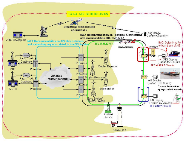
Figure 1.1
1.3 Project scope
1.3.1 What the project addresses
In AIS, a continuous and autonomous transmission of dynamic, static and voyage-related data for identification of ships is implemented by using text and/or binary data streams between transponders (installed on ships, or on shore AIS base stations). Only transponders of class-A type, which are installed on commercial ships and base stations ashore, are referred in the project context.
For AIS to operate in all environments and in all traffic situations a combination of VHF cellular broadcast, synchronization mechanisms and organization of transmissions is required.
This project addresses the VHF part of the AIS network, by providing information on how the service is supported, the AIS effective coverage over a designated AOI is calculated and achieved within an acceptable traffic load level.
In order to do that, a careful research and detailed examination of the applicable standards and techniques was done, including the nature of the messages exchanged, the core role that the SOTDMA protocol plays in AIS with its self-organizing technique, the major differences between the TDMA (Time Division Multiple Access) variants, and the concept of coverage.
The results of that background research are condensed in Appendix 1, where graphical representations were adopted as appropriate.
2 Work plan and methodology
2.1 Work plan and research methods for sources
2.1.1 Work plan
After establishing the project topic and defined its broad domain, important technical areas and features were identified and brought together during the research phase, including the message protocol used, the radio propagation, and the SOTDMA algorithm.
It was important to develop a work plan where each one of them, translated into a corresponding task, was sequentially, timely and properly investigated in order to concentrate the effort later on the project core: the VHF part of the AIS network.
A GANT chart, where the most important milestones were addressed[2], was produced early in the project development phase to reflect and integrate all such tasks, provide guidance, and allow adequate monitoring of the work progress.
A total budget of 320 working hours was established for all the activities to be carried out during the February-November 2004 period. An allowance of two weeks for eventual slippage was also included in the work plan.
By adopting log sheets for each work session, every task was carefully followed and annotated with the things to do next. In that way restarting the work in a new session was easily done without loosing control of the workflow.
The notes taken were invaluable in finding where the work was before and after the interruption, and about the identified points that would deserve a more in-depth analysis for work prosecution.
2.1.2 Research methods for sources
The literature search has been prepared by giving initial consideration to the identified project topic and scope, and compliance with the deadline.
Keywords (terms and phrases) such as ‘AIS’, ‘SOTDMA’, ‘self-organized’ and ‘radio propagation’ were identified and collected to serve as the basis for electronic database and library searching.
Later on, after comprehending the full topic context, the search was broadened by including another relevant term: ‘STDMA’ (there is no consistency in the terminology: both SOTDMA and STDMA refers to the same technique).
Major information resources for this project come from primary and secondary literature providers. In a couple of occasions direct contact with grey literature providers was established since there was no reliable information available elsewhere.
2.1.3 Assessment of sources of information used
A detailed assessment of the quality of information from each available source selected for this project was made using the PROMPT (Presentation, Relevance, Objectivity, Method, Provenance, Timeliness) methodology. Details of such assessment are available in Appendix 4.
2.1.4 Approach used to complete the project
The Safari (Skills in Accessing, Finding, and Reviewing Information) basic principles were adopted in order to identify and map the major sources of information that could contribute for the elaboration of this report.
From the moment that the project needs were identified and information was categorized as being essentially of on-line type due to my own, and project time limitations, the technology and techniques addressed in the project were abstracted from the application issues related with the safety of navigation, and a decision was taken to synthesize the relevant points of the project and translate them into appropriate chapters.
Then, two different approaches were taken:
First approach
Being a new subject, a gateway for technology, EEVL[3], and a patent site, SurfIP[4], were selected as material sources (Figure 2.7), where recent material was expected to be found, or redirection of searches could establish links with additional sites offering deeper information on this recent technology, such as papers, presentations, news, and applicable standards published.
Unfortunately, no many hits were achieved and those achieved were of poor quality, forcing me to change my focus to webcrawlers and search engines (www.metacrawler.com and www.hotbot.com).
The drawback of this changed approach was the large numbers of hits forcing me to filter the relevant material collected. Additional information came from exploring the links, or references they contained.
Too simple, unreliable or duplicated information was discarded, and the PROMPT methodology proved to be quite useful for that scope. The surviving material was paired with the different project areas (Figure 2.8), reassuring that there was enough material to start with, and later on to finish all the report areas.
Besides the standards published by IMO, ITU and IEC not freely available on the Internet and that were the most important sources for building-up my knowledge of the AIS technology before addressing the relevant project topic, most of the information was available from commercial (less reliable) sources.
Therefore, material available from them was used with caution, always double-checking first before using it.
Second approach
The Information Search Guide (from the Open University) was another approach used for access to electronic libraries. At the end it was a very time consuming, and not rewarding task due to the quite specialized nature of the project proposal. Only very generic, or too old articles on the subject were found using this methodology.
Overall, the strength of the first approach was the possibility of getting access to a large database. Its weakness was the quality of some material.
However, by refining the collected data, and finding its roots (links, references) a comprehensive, and useful collection of information for the project was made.
The second approach, which strength was the use of well-organized libraries, proved not to be adequate for the specialized project scope. Therefore its potential strength becomes its major vulnerability.
Finally, when I realized that still some information was not available on the Internet, such as data about maritime traffic in the area specified in the project, I had to address also the local community by asking for statistics and additional data, such as that included in Appendix 5, to the relevant Authorities acting as grey literature providers in this field.
2.2 Tools used in the project
2.2.1 Software tools
The following software tools were used for producing this report:
- Microsoft’s Project® was used from the beginning for planning and reworking the schedule of all the activities in this project.
- Microsoft’s Word® has been extensively used for writing this report, and for collecting all notes about it.
- Microsoft’s Excel® was used to create the report rate calculation table.
- Microsoft’s Equation Editor ® was used to produce the report equations.
- Microsoft’s Visio® was the drawing tool used to build-up the figures merged into the document.
- Adobe’s Acrobat® was used to read, download and extract figures from documents available from the Internet.
- Microsoft’s Internet Explorer® was used to browse the Internet.
3 The AIS network
3.1 The AIS service
3.1.1 Basic components of the VHF part of the network
The basic components embodied on the VHF part of the AIS network are:
· a shore base station including a transceiver (with TDMA receivers for each frequency, and a single transmitter), a communication processor and antenna. Other components not VHF-related are: a GPS position source, a UTC (Coordinated Universal Time) synchronization source, a protocol converter and a TCP/IP (Transmission Control Protocol/Internet Protocol) interface for the ground AIS network;
· the mobile transponders (or, just mobiles), installed on ships travelling in the area, with a suitable dedicated antenna.
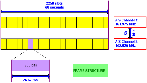
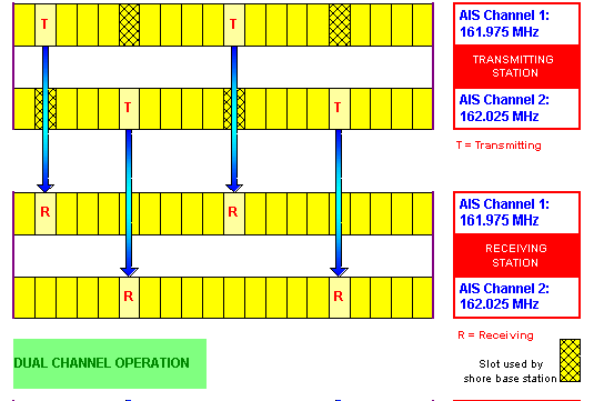
all of them sharing two common internationally adopted frequency channels (161.975 MHz and 162.025 MHz)[5]. It is common to install a redundant AIS shore station at each site to increase operational availability[6].
The fact that VHF supports cellular operation is not enough. The system requires the reuse of the frequency spectrum, and the support of RF discrimination due to the fact that radio cells overlap (see 3.1.3). To enhance discrimination it employs the following protocol and techniques:
· FM (Frequency Modulation)
· GMSK (Gaussian Minimum Shift Keying)
· HDLC (High-Level Data Link Control) packet protocol
3.1.2 VHF communications in a 4S environment
An artist’s view of the network communication, as described in a manufacturer’s leaflet[7] gives a good illustration of the 4S environment (see 3.1.4 below for the description).
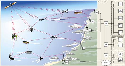
Figure 3.1
3.1.3 The mobile radio cell concept
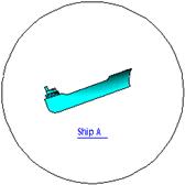
A radio cell is formed and defined by the omni directional LOS (line-of-sight) propagation range over the sea of a VHF transmission[8]. Even if transmission is omni directional, directional antennas could be used in shore AIS base stations to place coverage emphasis (better coverage) over a specific AOI.
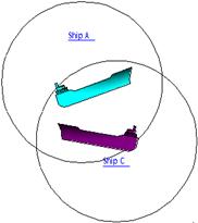
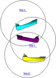
VHF transmissions are done by AIS base stations on shore, which usually take propagation range advantage of being placed well above the sea level, and by onboard ship transponders (mobiles). Both define radio cells in their vicinity that usually partially overlap when there are other mobiles travelling in the same area.
So, just because of the fact that the ship is moving, its own radio cell (the one it creates with its own transmission) is moving with it. When two or more ships are nearby, their own radio cells merge into an enlarged area of AIS coverage (see Appendix 1 - 1.2.5).
Enlargement of the radio cell created by a shore base station can also occur when distant mobiles, travelling at the limit of the propagation range of the base station, add their own radio cell to the radio cell of the base station enlarging the total AIS coverage beyond that initial limit.
3.1.4 Modes of operation of the AIS stations
From the functional point of view, AIS is a 4S system since it provides communication Ship-to-Ship and Ship-to-Shore, either in broadcast as well as in point-to-point mode.
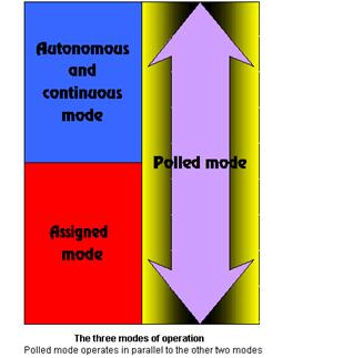 In autonomous mode each AIS station determines
its own transmission schedule, based on knowledge of past data link traffic,
and of future slot reservation done by other stations.
In autonomous mode each AIS station determines
its own transmission schedule, based on knowledge of past data link traffic,
and of future slot reservation done by other stations.
This means that each station automatically resolves contention with other stations.
In assigned mode, the station is assigned a transmission schedule by a controlling station.
Under this situation, a shore base station can assign a schedule to a mobile station (on a ship).
In polled mode, any station can make an interrogation that is followed by a response.
Figure 3.2
Naturally, as a consequence of the use of those modes of operation, slot selection has a direct impact on the efficiency with which the bandwidth is used, and on the channel performance itself.
3.2 AIS coverage
3.2.1 Consideration to shore station site selection
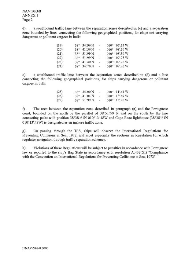
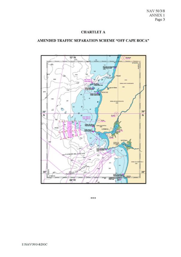
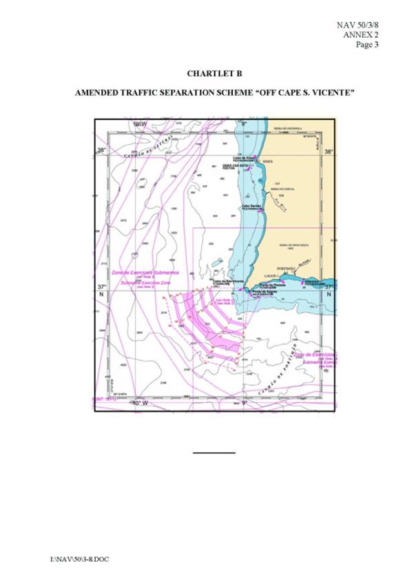
A maritime area for the simulation of AIS traffic was selected for this project. Along the Portuguese coastline, there are two navigation safety critical areas, where specific TSSs[9] (Traffic Separation Schemes) have been implemented (those of Cabo da Roca and Cabo de S. Vicente)[10]. They correspond to the zones where the traffic corridor (represented by the red colour in Figure 3.3[11]) along the Portuguese continental shore turns direction.
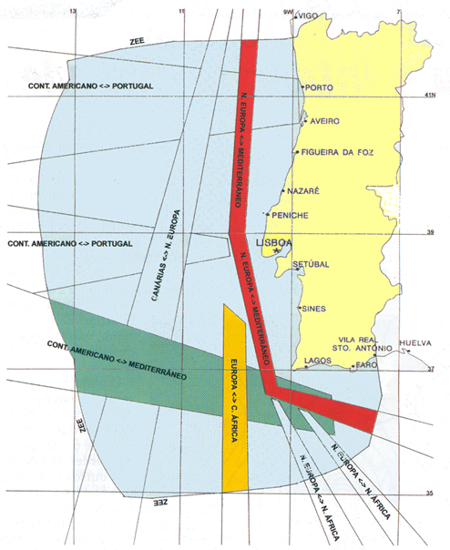
Figure 3.3
The traffic density (see 3.2.4) evidences how critical the areas are, which is reinforced by the pollutant and dangerous nature of most of the ship cargoes, and by the fact that these are areas where changes of ship’s course are expected to occur due to the proximity to geographical dangers.
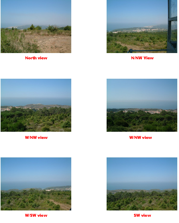
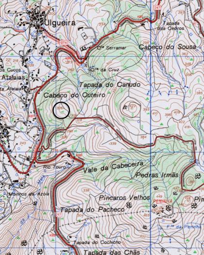
The coverage of the Cabo da Roca TSS was my choice for this project[12], and defined as the AOI. After that decision was made, I started looking for an appropriate location where to ‘place’ the shore AIS base station. A few site requirements were important to meet for that purpose, such as avoidance of potential environmental restrictions, easy road access, power availability, and free view of the horizon with no obstructions.
After a week searching the area, and a few phone calls to the local authorities, I found that the best site was in Serra de Sintra, just about 2.5 km east from the Cape, in a location defined by the geographical coordinates 38º 46.80’N / 009º 28.40’W at an altitude of 320 meters[13].
The site meets all the relevant requirements, and is within a forestry area where the impact of a small tower, with may be 10 meters for hosting the VHF antenna, would be negligible. On the other hand a minor road provides access to the site, which has already a small fire surveillance tower that eventually could be used for the project scope, reason why later approval of the site for this purpose is not expected to raise strong objections by environmental reasons. Unlimited view of the horizon is also available, avoiding the occurrence of diffraction[14] and reflection[15] phenomena, and vegetation would absorb VHF backward transmission over land[16].
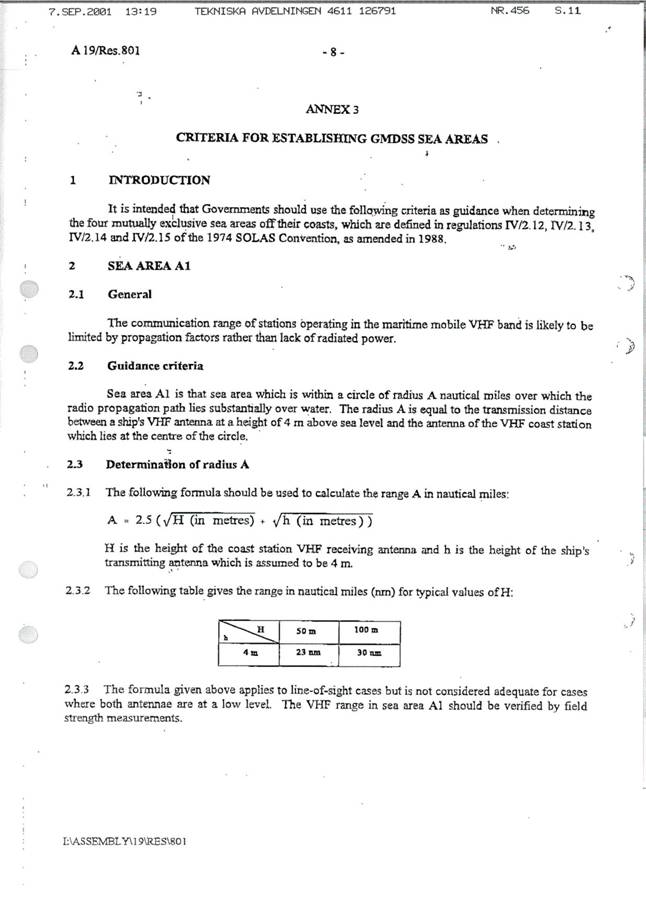
3.2.2 VHF Line-of-Sight (LOS) coverage calculation
The line-of-sight equation[17]:
|
|
where: D = theoretical LOS range in nm (nautical miles) |
|
|
h1 = height ASL (Above Sea Level) in meters for antenna of AIS shore base station |
|
|
h2 = height ASL (Above Sea Level) in meters for antenna of AIS mobile unit (ship) |
was adopted to calculate the nominal range achievable by the AIS shore base station. This deliberate approach is safe since consideration was not given to refraction due to atmospheric conditions and other physical variables that could extend the range.[18]
Therefore, assuming that a VHF antenna on a small ship will be placed 5 meters ASL and that the antenna height of the shore transmitting station at the selected site will be 330 meters ASL[19], we would then achieve a nominal base station range of 51 nm (94.5 km).
In order to validate the determined range as viable in terms of the power available being technically acceptable for the receiver to operate with a low BER (Bit Error Rate) (i.e. with a margin over the minimum requirements of a commercial equipment that has been found to be a signal level (receiver sensitivity) of –107 dbm[20]), I first determined the free space path loss (-115 dB) using the equation:
|
|
where: Lp = free space path loss over a determined distance |
|
|
f = frequency in MHz (162 MHz was used, as being the average between the two close AIS frequency approved channels) |
|
|
d = distance in nm between TX and RX antennas (51 nm as calculated above) |
The next step was to determine the losses and gains at both the transmitter and the receiver sides, having into account the estimated cable runs on both sides of the link, and the antenna gains, which was done in the following way:
On the transmitter (base station) side
|
Line loss: |
2 connectors @ -0.5 dB each |
- 1.0 dB |
|
|
15 meters of RG213 cable @ 31.16 dB/100 m[21] |
- 4.7 dB |
|
|
Total TX line loss |
- 5.7 dB |
|
Antenna gain: |
A directional antenna for the AOI was assumed[22] |
+ 6.0 dBi |
On the receiver (mobile transponder) side
|
Line loss: |
2 connectors @ -0.5 dB each |
- 1.0 dB |
|
|
5 meters of RG213 cable @ 31.16 dB/100 m[23] |
- 1.6 dB |
|
|
Total TX line loss |
- 2.6 dB |
|
Antenna gain: |
A typical omni directional antenna was assumed[24] |
+ 3.0 dBi |
I have also found that the typical base station transmitter power of the models (from the manufacturers addressed in endnote 20) in the market is 12.5W, corresponding to 41 dBm using the units of decibels relative to 1 mW(dBm). In this case, P=10log(12.5W/.001).
Finally, using the equation[25]
|
|
where: Pr = power available at the receiver input (mobile transponder side) (dBm) |
|
|
Pt = transmitter power (base station side) (dBm) |
|
|
Lp = free space path loss between isotropic antennas (dB) (see calculation done above, where Lp = -115dB) |
|
|
Gt = Transmitter antenna gain (dBi) |
|
|
Gr = Receiver gain (antenna) (dBi) |
|
|
Lt = Transmitter line loss between transmitter and transmit antenna (dB) |
|
|
Lr = Receiver line loss between receiver antenna and receiver input (dB) |
I got a value of 74 dBm which should be available at the receiver input (Pr), reassuring me that that there is a margin of almost 33 dB over the minimum requirement of the receiver (a –107 dBm signal level) for delivering messages with a low BER.
3.2.3 Reviewing of coverage calculation
For verification purposes, the range determined in 3.2.2 was checked using the equation[26]:
|
|
|
|
where: PL = path loss (dBm) ERP = effective radiated power (dBm) Sr = signal required (dBm) F = operating frequency (MHz) Ht = height of TX antenna (feet) Hr = height of RX antenna (feet) D = distance between antennas (statute miles) |
|
The following values were assumed:
F = 162 MHz
Ht = 330 m = 1083 feet
Hr = 5 m = 16 feet
D = 51 nm = 58.7 statute miles
The following calculations were made:
|
ERP |
= RF output power + TX Antenna gain – TX line loss |
|
|
= 41 dBm + 6 dBm – 6 dBm = 41 dBm; |
|
SR |
= (Receiver sensitivity + RX antenna gain) – (RX line loss + Fade margin) |
|
|
= -(107 dBm + 3 dBm) – (3 dBm + 3 dBm) = 104 dBm |
|
PL |
= ERP + Sr = 41 dBm +
104 dBm = 145 dBm |
The fade margin (-3 dBm) was arbitrarily selected for propagation over seawater. Solving for the distance between transmitter and receiver using the derived equation:
|
|
I got 51.83 statute miles, equivalent to 45 nm (still covering the AOI). Without the –3 dBm margin for fading we would get 61.6 statute miles, equivalent to 53.5 nm which is quite close and consistent with the value of 51 nm determined in 3.2.2.
Therefore, besides validating the calculation I did, I can conclude that the equation in the IMO Resolution A.801(19) for line-of-sight range calculation in sea areas has an allowance of 5% circa (the difference between 51 and 53.5 nm) for unpredictable variables of the propagation conditions.
The range between crossing mobiles (with antennas placed on both ships at the same 5-meter height), out of the coverage area of a base station, would be in accordance with the equation:
|
|
7.5 statute miles, equivalent to 6.5 nm, without considering any fading due to the short distance between ships (PL=148). The IMO equation, as addressed in the relevant document, is not suitable for communication between antennas at low height.
3.2.4 Creation of a traffic load scenario
There are no official statistics about the number of ships travelling along the Portuguese coastline. Non-official figures[27] point-out to 100 000 ships per year, which suggests an average of 274 ships per day. Most of the ships do not even touch Portuguese ports.
The AOI (see 3.2.1) is well within the base station radio cell determined by its coverage LOS range (see 3.2.2), as can be seen in Figure 3.4.
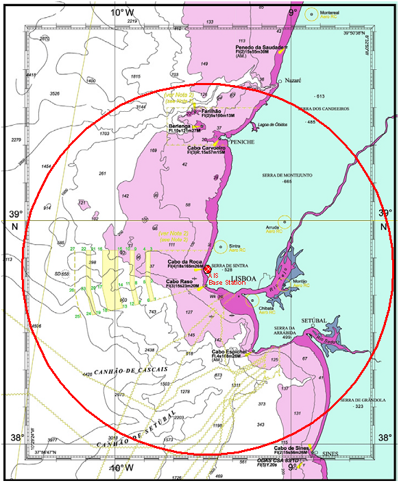
Figure 3.4
For this simulation I assumed that 80% of those ships move daily in the AOI, and - to enforce a worst-case scenario - I also assumed that 10% of them would be simultaneously travelling in the AOI, i.e. 22 ships.
A representative sample of a typical situation was created with a mixed set of AIS messages, in order to simulate a real traffic load situation in the AOI, based on the following assumptions[28]:
|
Message generation source |
Assumptions |
|
Ships moving |
22 ships will be simultaneously moving in the AOI generating messages 1, 2 or 3. Of these: a) 10% will be faster than 23 knots reporting every 2 seconds; b) 60% will be between 14 and 23 knots reporting every 6 seconds; c) 30% will be slower than 14 knots reporting every 10 seconds.
|
|
Ships at anchor |
15 ships will be simultaneously at anchor within the boundaries of the AIS shore station coverage area defined by its LOS range. Ships at anchor move and change heading depending on current and wind, reporting with messages 1, 2 or 3. Of these: d) 60% will be not moving faster than 3 knots reporting every 3 minutes; e) 40% will be moving faster than 3 knots reporting every 10 seconds.
|
|
Shore station |
It was estimated that almost 100% of ships at anchor would change heading even in small amounts due to the prevailing of fast changing wind conditions in the area. By safety reasons and to avoid data inconsistency at the VTS controlling station with radar data updated much faster within the period of a single radar antenna sweep, I decided to allow the AIS shore station to: f) interrogate (poll) every 31/3 seconds all the ships at anchor about their current heading by sending message 15; g) expect replies from all ships at anchor.
Besides I arbitrary decided in this scenario that the AIS shore station will: h) broadcast every 3 minutes differential corrections to the ships in the AOI (message 17); i) generate and broadcast reports with UTC time, date and position every 10 seconds (message 4); however, when it synchronizes with one or more mobiles its report rate (worst condition) reduces that interval to 31/3 seconds. The worst condition was assumed; j) generate and broadcast data link management messages every 10 seconds (message 20); k) distribute every hour, a safety-related broadcast message (message 14); l) send in average two long text messages per hour occupying three slots to each moving ship in the AOI; m) receive their acknowledgments to such text messages (I considered that an ACK (acknowledgement) was produced for each individual component slot of the message, which may be not the case since only one ACK for the full 3-slot message would do it); n) reply to each of the above ACKs with a base station ACK; o) send in average one long text message per hour occupying three slots to each ship at anchor in the AOI; p) receive their acknowledgments; q) reply to each of the above ACKs with a base station ACK.
|
3.2.5 Evaluation of radio cell saturation
On the basis of the messages generated (see Appendix 1 - 1.1.2 and 1.1.3) over the VDL (VHF Data Link) the traffic load has been calculated as follows:
|
Assumption |
Number of ships |
A Message every (seconds) |
Number of slots occupied by each message |
Report rate per minute |
|
a) |
2.2 |
2.00 |
1 |
66.00 |
|
b) |
13.2 |
6.00 |
1 |
132.00 |
|
c) |
6.6 |
10.00 |
1 |
39.60 |
|
d) |
9.0 |
180.00 |
1 |
3.00 |
|
e) |
6.0 |
10.00 |
1 |
36.00 |
|
f) |
15.0 |
3.33 |
1 |
270.27 |
|
g) |
15.0 |
3.33 |
1 |
270.27 |
|
h) |
1.0 |
180.00 |
1 |
0.33 |
|
i) |
1.0 |
3.33 |
1 |
18.02 |
|
j) |
1.0 |
10.00 |
1 |
6.00 |
|
k) |
1.0 |
3600.00 |
1 |
0.02 |
|
l) |
22.0 |
3600.00 |
3 |
1.10 |
|
m) |
22.0 |
3600.00 |
3 |
1.10 |
|
n) |
22.0 |
3600.00 |
3 |
1.10 |
|
o) |
15.0 |
3600.00 |
3 |
0.75 |
|
p) |
15.0 |
3600.00 |
3 |
0.75 |
|
q) |
15.0 |
3600.00 |
3 |
0.75 |
|
|
|
|
Total |
847.06 |
In a normal situation, due to the careful selection of the site, garbling and interference on the VDL should not be a problem. However, a precautionary decision was taken to round up the determined report rate from 847 to 900 reports per minute, thus allowing an additional pure arbitrary safety margin of six per cent.
The traffic load derived from the equation
|
|
where: T = Traffic load RR = Report Rate NC = Number of AIS channels (2) SC = Number of Slots per channel (2250) |
corresponds to a radio cell saturation of 20 per cent only, using both AIS channels, not representing by itself alone any kind of predictable risk for the successful operation of the AIS service in the AOI (see 3.4.1).
3.3 Ranges
3.3.1 Different range types and cell sizes
The IALA guidelines[29] cautionary advert us for the fact that “the area for safe reception of AIS messages from an AIS shore station is considerable smaller than the nominal coverage area of the shore station … due to the fact that the transmissions from the shore stations may be interfered with by transmissions from ships outside the coverage area of the shore stations and thus will not take into account the slot reservations made by the shore station”. It also endorses a fact of life that VHF broadcasts have a range of <40 nautical miles.
The receiving station detects one or more transmissions but cannot decode them, which is the definition for a ‘garbled slot’. Garbled slots tend to stay garbled and to increase in their number. That possibility increases as the channel load increases.
Increase of the channel load could also lead to a situation of no availability of slots, which would force the SOTDMA algorithm to intervene by reducing in a controlled way the effective operational range of the system.
I could say that SOTDMA builds-up an environment where a constantly changing population dynamically determines the cell size. Therefore, I would classify ranges in three types, corresponding to different cell sizes:
· Nominal range: the theoretical range calculated by applying the LOS equation;
· Operational range: theoretical range at which successful decoding of a transmission is achievable, taking into account additional factors such as path loss;
· Controlled-reduced operational range: reduced system range controlled by the SOTDMA algorithm due to increase of the channel load.
3.4 Traffic load
3.4.1 Validation
The fact that a 20% traffic load was determined (see 3.2.5) using two AIS channels, would enforce that - in the case of loss of one channel - that traffic would be handled by a single channel that would be then operating at a load rate of 40% (900 slots into a single channel).
That figure is still quite acceptable, and its consistency was reviewed against an example of dangerous AIS overload rate[30].
3.5 Other
3.5.1 The slotted Aloha problem
When mobile transponders are not organized in terms of slot allocation between themselves, they will select what seem to be the available slots, i.e. they select slots at random which is defined as the slotted Aloha[31] behaviour. This situation occurs when due to severe VHF propagation limitation two ships cannot receive each other.
Without having previous knowledge of it, they are eventually competing for the same slot utilization.
A garbling condition occurs when a third ship, eventually receiving the other two, automatically reuses slots (as part its normal AIS operation) that are already in parallel (but different scope) use by the other two ships. This situation leads directly to link overload, since garbled slots will continue to occupy space, not being reused.
Therefore, when cell allocation is unorganised we have a situation in which the required capacity will be different from the capacity that is actually used.
Under those special circumstances, where the mobiles will be picking their own slots without any organization, this corresponds to what is known as the slotted Aloha problem which is the opposite of what AIS represents: autonomous allocation of slots in an organized way, where each transponder schedules itself to transmit, based on mutual knowledge of intended actions from other mobiles, and the VDL history.
The slotted Aloha problem has been referenced here, because it reinforces the role of self-organization within AIS, and shows how important it is to care about it when planning for a VHF shore network.
There might be geographical constraints ashore, for example around a geographical mountainous corner, which would prevent mobiles to receive each other. However, within the scope of the current work there is no reason for further developing this topic.
4 Future applications of AIS and SOTDMA
4.1 Maritime applications
4.1.1 Aids-to-Navigation (AtoN)
Authorities responsible for AtoN in the different Countries can take advantage of the AIS technology and message handling capability for remotely monitoring and controlling such aids (lighthouses, buoys), and disseminate information about their location and operational availability to ships travelling in the area, which can then have that information automatically overlaid in their charting displays.
An AIS transponder will be installed in each AtoN, and use the facilities provided by the format of Message 21 of the AIS protocol defined by IALA[32] for transmitting the required data, that will include the GPS position of the AtoN (it could also be drifting in the case of a lost buoy), its battery status and working condition[33].
Data transmitted on the two common VHF channels assigned to AIS would then be collected by the ground base stations and sent to the appropriate Authorities, which by using a suitable real-time processing system could then send back warnings to the navigation in the area using Message 14 (a safety-related message) when a danger occurs due to a failure of a single AtoN.
Other AtoNs, including meteorological and tidal sensors, are also being addressed as additional potential beneficiaries of the AIS system.
4.1.2 Long range AIS
AIS is today a standard that is currently being implemented to cover in a very short time most of the world coastal and port areas. To extend that coverage further over the oceans, the AIS has to overcome the VHF range limitation.
In that sense, there are already mobile AIS transponders with interfaces prepared for long range AIS[34] where the ships will exchange data with mobile ground stations via satellite systems, such as Inmarsat C, and HF (High Frequency) radio systems in the 3-30 MHz frequency band. The only thing that is missing for the AIS long-range service to be operable is regulation from the competent Authorities.
With long range AIS search-and-rescue operations will be enhanced, and full tracking of ships can be accomplished all over the world.
The need for tracking in high seas does not imply fast rate reports which, if in place, would dramatically increase the communication cost.
Reports can be made at an hourly or slower rate, unless by safety reasons (storms, dangers on board, etc.) faster rates are required by initiative of the ship’s captain, or following an automatic request addressed to a single ship or a group of ships (polling) by an Authority, or ship’s owner on ground[35].
4.2 Aviation
4.2.1 VDL Mode 4
The extension of the digital VDL concept to aeronautical applications based on the SOTDMA for transmission of ADS (Automatic Dependent Surveillance) messages in a Broadcast (ADS-B)[36] or Contract (ADS-C) mode was being studied by ICAO (International Civil Aviation Organization) and Eurocontrol since almost ten years. Finally, it was approved in 2001 as a standard.
Major future applications will be done with transponders installed aboard aircraft and airport vehicles with access to runways, with the aim of improving surveillance, air navigation and air traffic control[37].
5 International statutory Bodies and regulations
5.1 International Bodies
5.1.1 Standardization
The following figure identifies all the International Authorities that are directly responsible for the standardization of AIS in each specific area:
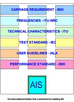
Figure 5.1
5.1.2 Certification
There are a few national institutions that certify the compliance of the AIS equipment produced by the different manufacturers with the applicable standards. Within the European Union the following three laboratories were identified:
|
Institution |
Current valid certifications issued[38] |
|
BSH, in |
19 |
|
QinetiQ Ltd, in |
1 |
|
|
7 |
5.2 Regulations
5.2.1 AIS current applicable standards and recommendations
The current AIS relevant documents issued by International Bodies are:
· Carriage requirement
IMO:
Regulation 19 (on the carriage requirement for AIS starting from July 2002)
· Frequencies:
ITU:
Radio Regulations, Appendix S18, Table of Transmitting Frequencies in the VHF Maritime Mobile Band, WRC, Geneva, November 1997
· Technical characteristics:
ITU:
Recommendation
on the Technical Characteristics for a Ship-borne Automatic Identification
System (AIS) Using Time Division Multiple Access in the Maritime
IALA;
Technical Clarifications of Recommendation ITU M.1371-1, Edition 1.4, December 2003 (pending a future revision of the ITU Recommendation)
· Test standard:
IEC:
Standard 61993 Part 2: Class A Ship-borne equipment of the Universal Automatic Identification System (AIS) – Operational and Performance requirements, methods of testing and required test results, 2001
· User guidelines:
IALA:
Guidelines on the Universal Automatic Identification System (AIS), Edition 1.1, December 2002
IALA:
Guidelines on AIS as a VTS tool, December 2001
IALA:
Recommendation on the provision of shore based Automatic Identification Systems (AIS), Edition 1.1, December 2002 (A-123)
IALA:
Recommendation on Automatic Identification System (AIS) Shore Station and Networking Aspects relating to the AIS Service, Edition 1.1, December 2003 (A-124)
· Performance standard:
IMO:
Recommendation on Performance Standards for a ship-borne Automatic Identification System (AIS), (MSC 74(69) Annex 3), May 1998
5.2.2 Carriage requirements
The current IMO mandatory AIS carriage requirements[40] address all:
· New passenger ships and new cargo ships above 300 t built after 1 July 2002
· Passenger ships and tankers on international voyage after 1 July 2003
· Cargo ships above 50 000 t, in international voyages after 1 July 2004-07-31
· Cargo ships 10 000 – 50 000 t, in international voyages after 1 July 2005
· Cargo ships 3 000 – 10 000 t, in international voyages after 1 July 2006
· Cargo ships 300 – 3 000 t, in international voyages after 1 July 2007
· Ships > 300 t, not in international voyages after 1 July 2008
6 Conclusion
This reports fulfils its initial scope of demonstrating and validating AIS coverage and operation over a pre-defined maritime area of interest (AOI).
It also shows that there is enough link budget to cope with the maximum data load of a scenario that was assembled using reliable estimated movements of ships in the area. Whenever data was not sufficient or unavailable, always the worst-case scenario was addressed, in order to minimize risk.
It was demonstrated that the level of the RF signal expected within the area of interest is compatible with good quality communication.
Further quality analysis out of the scope of this work would be required to assess quality at an appropriate level. From the figures already identified, in terms of load and propagation over a clear sea area, it is not expectable the appearance of garbling conditions, which if present could have a serious impact either in the link quality as well as in the shrinking of the cell size due to the combination of the self-organization with the slotted-Aloha problem referenced in the text.
Shrinking the cell size while maintaining the report rate is the way in which AIS deals with an overload situation, i.e. it autonomously maintains its integrity and stability without compromising the report rate.
Data sent by each ship is not usually acknowledged. Exchange of text messages required by applications implies a two-way communication and handshaking, which would have an impact on the link load.
The work done, starting at the site selection for the installation of a base station, can serve as an initial basis for approaching the installation of similar additional base stations along the coastline.
The implementation of such stations, even if carefully planned, will have to account for the coordination of slot allocation since neighbouring base station cells will overlap in their boundaries, and there could be a need for slot reuse of slots previously allocated to distant ships, in order to keep slot integrity within the area. Technically, even if the base stations address this automatically, additional messages will be added to the VDL.
A single base station constitutes a single point of failure in a network. Dual, redundant, base stations should be installed at each site in order to keep reliability high.
Travelling VHF cells is a concept strictly associated with the inherent capability of ships establishing AIS temporary itinerant networks over the sea, when at least two ships travel in the vicinity of each other.
Travelling cells can associate between themselves, when one of them is within the range of another cell, including those ashore, extending in that case the shore base station cell (and the AIS coverage) circumstantially farther out of the LOS restriction characteristic of VHF propagation.
Long range AIS is not a mirage and when formal agreement is granted by the International Authorities to its implementation the current VHF LOS restriction will no more apply.
7 Acronyms
List of acronyms used in this report
|
4S |
Ship-to-Ship and Ship-to-Shore |
|
ACK |
Acknowledgment |
|
ADS |
Automatic Dependent Surveillance |
|
AIS |
Automatic Identification System |
|
AOI |
Area of Interest |
|
ASCII |
American Standard code for Information Interchange |
|
ASL |
Above Sea Level |
|
AtoN |
Aids-to-Navigation |
|
BER |
Bit Error Rate |
|
ECDIS |
Electronic Chart Display and Information System |
|
ETA |
Estimated Time of Arrival |
|
EUROCONTROL |
European organisation for the Safety of Air Navigation |
|
FATDMA |
Fixed Access Time Division Multiple Access |
|
FM |
Frequency Modulation |
|
GMSK |
Gaussian Minimum Shift Keying |
|
GNSS |
Global Navigation Satellite System |
|
GPS |
Global Positioning System |
|
HDLC |
High-Level Data Link Control |
|
HF |
High Frequency |
|
IALA |
International Association of Lighthouse Authorities |
|
ICAO |
International Civil Aviation Organization |
|
IEC |
International Electrotechnical Commission |
|
IMO |
International Maritime Organization |
|
IPTM |
Instituto Portuário e dos Transportes Marítimos, the Portuguese maritime Authority |
|
ITDMA |
Incremental Time Division Multiple Access |
|
ITU |
International Telecommunication
|
|
KM |
Kilometres |
|
LOS |
Line-of-Sight |
|
MMSI |
Maritime |
|
NI |
Nominal Increment |
|
NM |
Nautical miles |
|
NS |
Nominal Slot |
|
NSS |
Nominal Start Slot |
|
NTS |
Nominal Transmission Slot |
|
PROMPT |
Presentation, Relevance, Objectivity, Method, Provenance, Timeliness |
|
RATDMA |
Random Access Time Division Multiple Access |
|
ROT |
Rate of Turn |
|
RR |
Report Rate |
|
SAFARI |
Skills in Accessing, Finding, and Reviewing Information |
|
SAR |
Search and Rescue |
|
SI |
Selection Interval |
|
SOTDMA |
Self Organized Time Division Multiple Access |
|
STDMA |
See SOTDMA |
|
TCP/IP |
Transmission Control Protocol / Internet Protocol |
|
TDMA |
Time Division Multiple Access |
|
TSS |
Traffic Separation Scheme |
|
uAIS |
Universal Shipborne Automatic Identification System (precursor to AIS) |
|
UTC |
Coordinated Universal Time |
|
VDL |
VHF Data Link |
|
VHF |
Very High Frequency |
|
VTS |
Vessel Traffic Services |
|
WRC |
World Radiocommunication Conference |
8 Notes, references and bibliography
[1] IALA Technical Clarifications on Recommendation ITU-R M.1371-1, Edition 1.4, December 2003, available from http://www.iala-aism.org
[accessed October 26, 2004]
[4] Available at the following URL: http://www.surfip.gov.sg/sip/site/sip_home.htm [accessed November 8, 2004]
[5] These frequencies are defined in Appendix S18 of Radio Regulations as quoted in the IALA Technical Clarifications on ITU Recommendation ITU-R M.1371-1, Edition 1.4, December 2003, available from http://www.iala-aism.org [accessed October 26, 2004].
[7] Leaflet from Saab Transpondertech, available for download at: http://products.saab.se/PDBWeb/GetFile.aspx?pathtype=ProductFiles&filetype=Files&id=1467 [accessed November 8, 2004].
[8] I am not addressing the portion of that propagation over land, where it is usefulness since AIS is only intended for maritime use.
[9] Traffic Separation Scheme, or TSS as abbreviated, is an area agreed by the IMO (International Maritime Organization) where ships travel within clearly defined lanes for the purpose of safety of navigation, and where ship’s reporting is mandatory. Further information is available within the scope of Rule 10 of the Convention on the International Regulations for Preventing Collisions at Sea, 1972 (COLREGs) at: http://www.imo.org/home.asp [accessed November 8, 2004] searching for Collision Regulations within the Site Index.
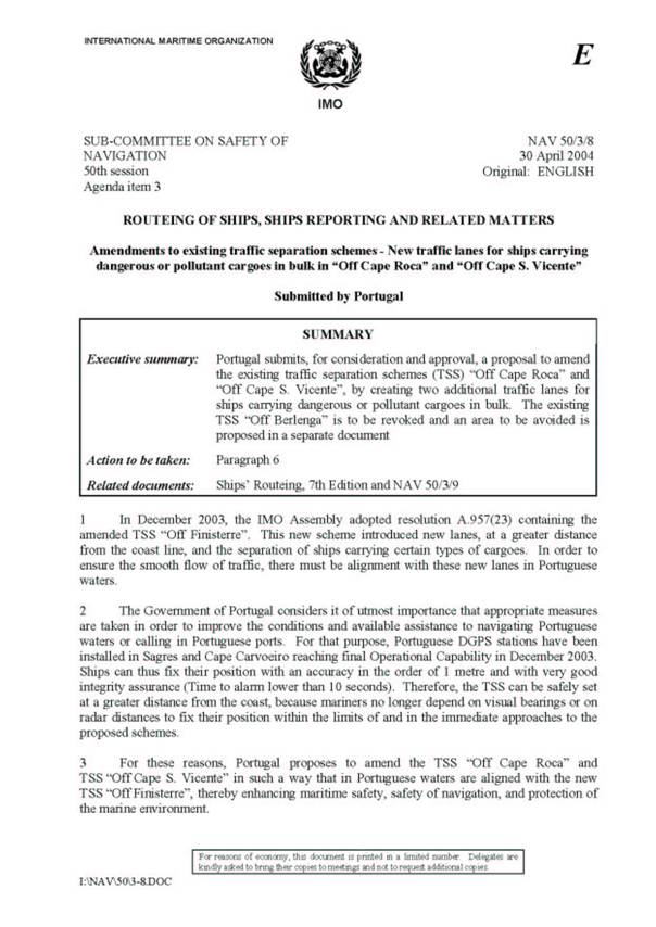
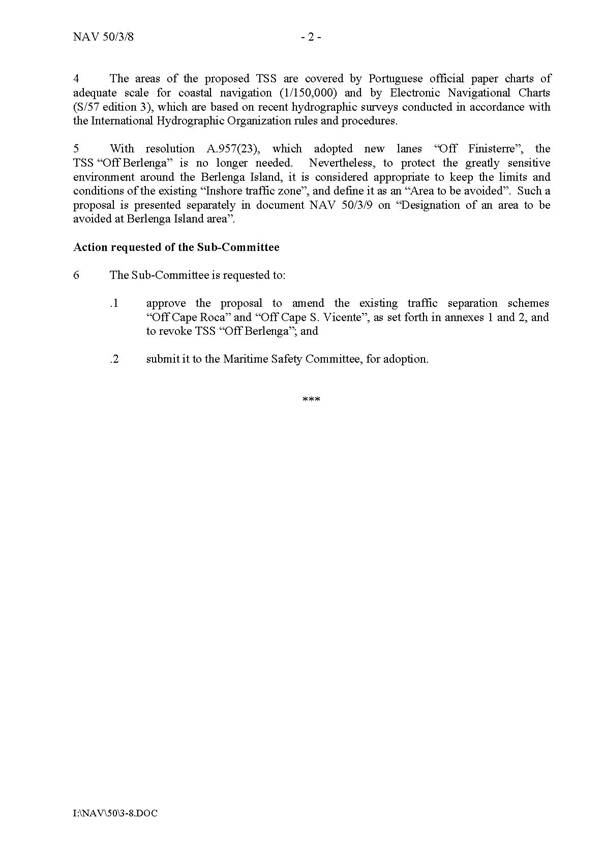
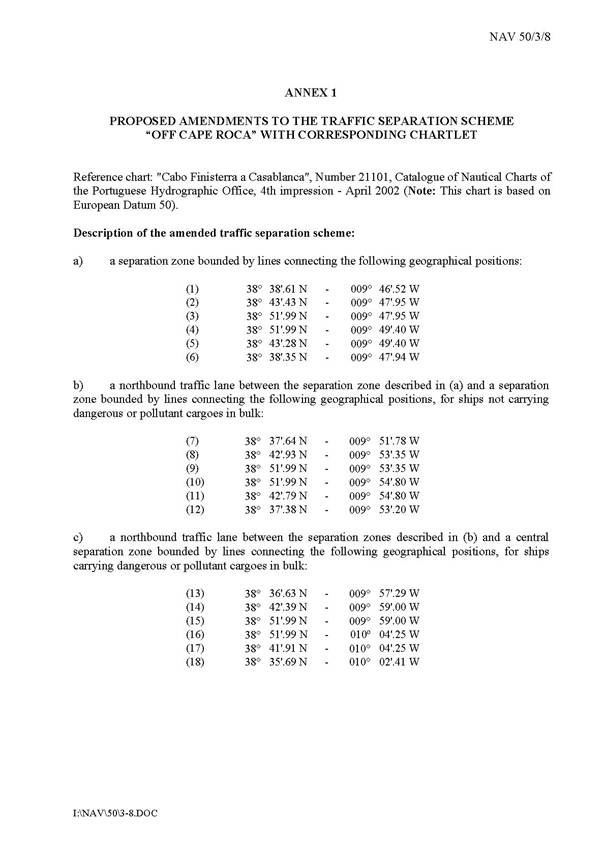
[10] The Portuguese Government has submitted recently to IMO a proposal for the amendment of the Traffic Separation Schemes of Roca and S. Vicente, in order to send them further away from the coastline, avoiding the need of and eliminating the third TSS (Berlengas) currently in place (see Appendix 5).
[11] This figure was extracted and worked out from the Marvil site (http://gasa.dcea.fct.unl.pt/infozee/en3.1.htm [accessed June 24, 2004]).
[13] Coordinates were determined with a hand held GPS facility available in a mobile phone, and altitude was determined with a hand held separate bar pressure altimeter, since GPS-derived altitude data was not reliable providing inconsistent sequential readings.
[14] Diffraction is the ‘change of direction of waves to bend around corners and spread as they encounter obstacles’ as defined in http://maxwell.byu.edu/~masong/HTMstuff/C13A3.html [accessed September 29, 2004].
[15] Reflection is the abrupt change in direction of a wave front at an interface between two dissimilar media so that the wave front returns into the medium from which it originated as defined in http://www.its.bldrdoc.gov/fs-1037/dir-030/_4497.htm [accessed September 20, 2004].
[17] This equation is defined in Annex 3 of IMO Resolution A.801(19)for line-of-sight range calculation in sea areas (please see Appendix 7).
[18] The result
has been validated against the generic equation ![]() for
radio line of sight free space calculation provided at http://www.pacificcrest.com/downloads/application_notes/AppNote_UHF_VHF_Calc.pdf [accessed
July 31, 2004], where Hr is the height of the RX antenna and Ht
is the height of the TX antenna, both in feet. With that equation that does not
accounts for variables (transmitter power, receiver sensitivity, line losses,
and antenna efficiency), the maximum theoretical range would be 69.5 statute
miles, corresponding to 60.4 nm.
for
radio line of sight free space calculation provided at http://www.pacificcrest.com/downloads/application_notes/AppNote_UHF_VHF_Calc.pdf [accessed
July 31, 2004], where Hr is the height of the RX antenna and Ht
is the height of the TX antenna, both in feet. With that equation that does not
accounts for variables (transmitter power, receiver sensitivity, line losses,
and antenna efficiency), the maximum theoretical range would be 69.5 statute
miles, corresponding to 60.4 nm.
[19] This height corresponds to the altitude of the site added by the height of the tower where the antenna will be placed.
[20] This receiver sensitivity figure was found to be the same in the commercial literature available for the operation of the equipments produced by two leading AIS base station and mobile transponders manufacturers (Seatex and Saab TransponderTech). See http://www.kongsberg-seatex.no/pdf/ais_basestation.pdf and http://products.saab.se/PDBWeb/GetFile.aspx?pathtype=ProductFiles&filetype=Files&id=1461 [both accessed September 18, 2004].
[21] The average attenuation value of 9.5 dB/100 feet found for the RG213 50-ohms cable from the table at http://www.astronantennas.com/transmission.html [accessed October 31, 2004] was converted into a value of 31.16 dB/100 m.
[22] From the range of antennas of the Finish manufacturer Aerial Oy (http://www.aerial.fi/aerial-vhf.pdf [accessed October 31, 2004]) there are several directional units that could be used for the Roca TSS, ensuring an optimal coverage of the area with gains between 10 dBi (for a narrow E-plane beamwidth of 14º) and 2 dBi (for an E-plane beamwidth of 80º). An acceptable antenna with a E-plane beamwidth of 70º and a 6-dB gain was selected as representative for the calculation.
[23] The average attenuation value of 9.5 dB/100 feet found for the RG213 50-ohms cable from the table at http://www.astronantennas.com/transmission.html [accessed October 31, 2004] was converted into a value of 31.16 dB/100 m.
[24] One of such antenna types from a known manufacturer can be found at http://cyber-bridge-marine.com/shakespeare_antennas.htm [accessed October 31, 2004].
[25] The equation is quoted in the document: VHF/UHF/Microwave Radio Propagation: A Primer for Digital Experimenters, by Barry McLarnon, available from http://www.tapr.org/tapr/html/ve3jf.dcc97/ve3jf.dcc97.html [October 31, 2004]
[26] This equation is derived and consistent with the equation for path loss available at http://www.pacificcrest.com/downloads/application_notes/AppNote_UHF_VHF_Calc.pdf [accessed July 31, 2004].
[27] The Marvil site (http://gasa.dcea.fct.unl.pt/infozee/en3.1.htm [accessed June 24, 2004]) estimates based on figures gathered in 1986 that an average of 100 ships/day are passing along the continental shore of Portugal. However, estimation provided by IPTM (Instituto Portuário e dos Transportes Marítimos), the local Portuguese Authority implementing the Coastal Vessel Traffic Services, when I tried to check the Marvil figure with them by phone on June 28, 2004, currently raised it to almost 100000/ships/year. I decided to adopt the IPTM estimation, being more recent and coming from a reliable source.
[28] Annex A to IALA Recommendation A-124, under the title Services Operating in the VDL (VHF Data Link) simultaneously, provides a good summary of all AIS message types that can be generated by base stations and mobiles. This project does not covers such a wide number of types, but it approaches reality since the traffic load situation was calculated based on stringent worst-case scenarios for all the included messages. See http://site.ialathree.org/ [accessed October 10, 2004] navigating through AIS/IALA Recommendations.
[29] IALA Guidelines on ship-borne Automatic Identification System (AIS), Volume I Part II: Technical Aspects of AIS, Edition 1.1, December 2002. See http://site.ialathree.org/ [accessed October 10, 2004] navigating through AIS/IALA Guidelines.
[30] AIS as Part of Integrated Systems – Manufacturers’ Point of View, Dr. Volker Koehler, November 2003 (see Appendix 7). Paper presented to the AIS03 Conference organized by the Royal Institute of Navigation.
[31] In pure Aloha, a user can transmit at any time but risks collision with other users' messages. "Slotted Aloha" reduces the chance of collisions by dividing the channel into time slots and requiring that the user send only at the beginning of a time slot. Aloha was the basis for Ethernet, a local area network protocol (as defined in http://www.webopedia.com/TERM/A/Aloha.html [accessed October 31, 2004].
[33] A manufacturer’s Internet site provides good examples of this type of emerging application. See http://www.zenilite.co.jp/english/Home%20page.htm [October 26, 2004]
[34] Some manufacturer sites, such as those of Seatex and Saab TransponderTech referenced in this document, provide downloadable leaflets of their mobile transponders where such interfaces are already described as commercially available. A paper on the subject is available from http://www.imisglobal.com/papers.htm [accessed October 31, 2004].
[35] There are a few sites that offer already some worldwide tracking services. One of them can be visited at http://www.portlinkweb.com/be/main.htm [accessed November 5, 2004].
[36] A page containing several links for ADS-B information is available at http://www.ads-b.com/ [accessed October 31, 2004].
[37] Saab Transpondertech, one of the leading AIS manufacturers, has a page dedicated to VDL Mode 4 applications at http://www.transpondertech.se/node5551.asp [accessed October 30, 2004].


